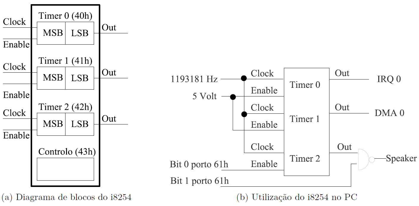
Figure 1: The PC timer: i8254.
The objective of this lab is twofold. First that you learn how to use the PC's timer. Second that you understand the concept of interrupt, and learn how to use it in the context of this lab.
This handout, like all other LCOM handouts, is structured as follows. After this section with the generic objectives, Section 2 summarizes what you have to do. Next, we present information on the I/O device that is the object of the lab, and that is relevant to the execution of the lab. This is followed by notes on aspects of the Minix operating systems, that you need to use in the lab. The following section details the work that you have to develop. Then we provide some details on how to compile, configure and run your program. Instructions regarding the submission, usually close the handout.
Write in C language several functions to use the PC's timer. The goal is to develop a generic module that will be used to create a library, which you will be able to use in the course's project.
Like in the previous lab we specify the prototype of functions that operate on the I/O device. However, for testing/evaluation purposes you will also have to develop a set of test functions, whose prototype we specify. In future labs, we will specify only the testing functions and you will have to design the functions for operating on the I/O device.
Specifically, in the first class of this lab, you shall develop the following test functions:
These three functions are declared in header file timer.h, and file timer.c contains their implementation stubs. You may find it convenient to add your test code to these files; this way you will avoid mistakes in their definition. Section 6 describes what these functions should do, and specifies the functions that you have to develop to implement them. You can also read the documentation generated by doxygen for the timer module.
Furthermore, you will also have to develop the function main(), which must be in a file named lab2.c. This will allow us to use our own main() without having to manually edit your files. Nevertheless, we will grade your lab2.c, and you should try to follow the approach used in the code we provided for Lab1.
To create a working copy for this lab in the home directory of user lcom in the Minix 3 VMPlayer image of the lab's PCs, you can follow the steps suggested in the SVN tutorial. I.e. you can:
lab2 to the SVN repository of your project on Redmine /home/lcom/lab2/ of the Minix image a working copy of the directory tree rooted at lab2, that you have just imported.update command. Otherwise, you can apply SVN's checkout command to the directory tree rooted at lab2. As in Lab 1, you should commit your changes as you develop and test your functions.
You should run as user root only to install the configuration file lab2 in /etc/system.conf.d/ and to run your program with service. Otherwise, you should always use user lcom.
This lab is planned to be carried out in two classes. The goals for the first class are as follows:
timer_test_config()), and associated functions.
timer_test_config()) and timer_test_square()) and associated functions. This way you'll have some more time to implement timer_test_int() in the second lab.Therefore, for the first class, you should read this handout, except Sections 4 and 5.2, which concern interrupts, the focus of the second class. You should also read the i8254 data sheet, especially the section on its programming interface, and the material that was planned for the lecture of September 30th.
For the second class, you should read also Sections 4 and 5.2, as well as the material about interrupts that will be presented in the lectures
Although we will grade only the contents of your SVN repository by the deadline of the lab, we encourage you to regularly commit your work as you implement and test the required functions. Remember that one of the goals of this course is that you learn how to use tools typically used in the development of large programs, including version control systems, and you will receive credit for it.
Every PC "has" an i8254 an IC with 3 timers, whose block diagram is shown in Figure 1. In this lab, you'll use timer 0 only. You must not change timer 1 configuration.
The 3 timers are identical and operate independently of one another. Thus we will describe only one timer.
A timer has a 16 bit counter, two input lines, Clock and Enable, and an output line Out. The Enable line is used to enable/disable the timer. When a timer is enabled, the value of its counter is decremented by one on every pulse of the Clock line. The value of Out depends on the counter's value and on the operating mode.
The i8254 supports several modes, but in this lab you will use only mode 3, square wave generator. In this mode, the Out line is high initially and until the counter reaches half of its initial value. It then goes low until the counter reaches zero, at which time the counter is reloaded with its (pre-programmed) initial value, Out is set to high and the cycle begins again. Thus, in mode 3, the timer generates a square wave with a frequency given by the expression clock/div, where clock is the frequency of the Clock input and div is the value loaded initially in the timer.
Each timer has a 16 bit counter, which may be both read and written. Furthermore, the i8254 has a single control register that can be written only, and that is used to configure the operation of all timers.
Each timer is programmed independently of the other timers. Programming a timer requires two steps:
The format of the control word (a 8-bit value) is shown in Table 1.
| Bit | Value | Function |
| Select counter | ||
| 7,6 | 00 | 0 |
| 01 | 1 | |
| 10 | 2 | |
| Type of Access | ||
| 5,4 | 01 | LSB |
| 10 | MSB | |
| 11 | LSB followed by MSB | |
| Operating Mode | ||
| 3,2,1 | 000 | 0 |
| 001 | 1 | |
| 010 | 2 | |
| 110* | ||
| 011 | 3 | |
| 111* | ||
| 100 | 4 | |
| 101 | 5 | |
| Counting mode | ||
| 0 | 0 | Binary (16 bits) |
| 1 | BCD (4 decades) |
Thus, bits 6 and 7 specify which timer to program. Bits 1, 2 and 3 specify the operating mode. Bit 0 specifies whether the counter is a binary or a BCD counter, i.e. whether the inital value should be interpreted as a binary or a BCD value. Bits 4 and 5 specify how the initial value is loaded. The following paragraph provides some more details regarding these bits.
Although the counters are 16 bits, the i8254 has only 8 data lines. Thus to load the initial value of a counter, the LSB and the MSB must be written separately. The i8254 allows loading either of these bytes, or both of them. In the latter case, the LSB must be loaded first. Which bytes of the counter will be loaded in the second step is specified by bits 4 and 5.
Reading a timer's configuration requires a special command: the Read-Back command. This command allows not only to read the programmed mode, but also the count value and the current state of the OUT line of the selected timer(s). Table 2 shows the format of the Read-Back command.
| Bit | Value | Function |
| 7,6 | 11 | Read-Back Command |
| 5 | COUNT | |
| 0 | Read counter value | |
| 4 | STATUS | |
| 0 | Read Programmed Mode | |
| 3 | Select Counter 2 | |
| 1 | Yes | |
| 2 | Select Counter 1 | |
| 1 | Yes | |
| 1 | Select Counter 0 | |
| 1 | Yes | |
| 0 | 0 | Reserved |
Like the Control word, the Read-Back command is also written to the control register. The value of bits 6 and 7, allow the i8254 distinguish between a control word and a read-back command.
Selection of the counters is now done with the help of a bit mask -- bits 1 to 3 --, thus allowing to retrieve information regarding different timers with a single command.
Likewise selection of the data to read uses a bit mask -- bits 4 and 5,-- thus allowing to read either the count value or the programmed mode, or both.
In this lab, you need only to read the configuration of one timer at a time. Thus after writing the appropriate Read-Back command to the control register, the configuration can be obtained by reading from that timer. You can find further details on the operation of the Read-Back command on the corresponding Section on pg. 7 of the i8254 data sheet.
Table 3 shows the format of a timer's Status byte:
| Bit | Function |
| 7 | Output |
| 6 | Null Count |
| 5, 4 | Type of Access |
| 3,2,1 | Programmed Mode |
| 0 | BCD |
That is, bits 0 to 5 contain the corresponding bits of the last control word affecting the operation of that timer.
Bit 7 contains the current value of the timer's OUT line. Finally, bit 6 is related to the reading of the counting value, and we do not provide further details. You can find them in the i8254 data sheet.
The PC uses each timer for a different purpose. Nevertheless, all timers use the same clock signal with frequency 1193181 Hz.
As shown in Figure 1, the output of timer 2 is connected to the PC speaker, and is used to generate tones by generating a square wave of an audible frequency. For example, to generate a 1000 Hz tone, the timer must be programmed to operate in mode 3, with an initial value of 1193.
Furthermore, to enable the speaker, you must set to 1 both bits 0 and 1 of I/O port 0x61 (SPEAKER_CTRL) . As shown in Figure 1, bit 0 is connected to the GATE of Timer 2 and if low, it will disable the timer. In addition, the OUT line of timer 2 is not connected directly to the speaker, instead it is gated via a NAND, whose other input line comes from bit 1 of port 0x61. Thus, unless that bit is set to 1, the input to the speaker will always be high, and no tone will be generated.
Note: On most laptops VMPlayer does not emulate the speaker. Therefore, you will not be able to hear any tone, even if you correctly configure the Timer 2.
Figure 1 also shows that the output of the timer 0 is directly connected to line IRQ0 of the PC's interrupt controller. It is usually programmed in mode 2, to generate a more or less stable time reference that can be used by the operating system to measure time with a resolution of a few milliseconds. In Section 4 we describe the interrupt mechanism used by the PC, and in Section 5 we describe the use in Minix 3 of the interrupts generated by the timer 0.
The registers of the i8254, like those of most other PC's I/O devices, are mapped in the I/O address space of the PC's processor. The address of the control register (TIMER_CTRL) is 0x43, the address of timer 0 is 0x40 (TIMER_0) and the address of timer 2 is 0x42 (TIMER_2). Although the counters of these timers are 16 bit, all these registers are 8 bits, and access to the MSB and the LSB of each counter is done as described above in Section 3.2.
Note: This section describes the PC's priority interrupt handling based on the i8259. Although current systems support a more advanced mechanism (the APIC), it is still possible to use the older interface.
In the PC, all HW interrupts are processed using the i8259 IC, the priority interrupt controller (PIC). This IC has 8 interrupt request (IRQ) lines which are connected directly to I/O devices. These lines have an implicit priority: IRQ line 0 has the highest priority, next comes IRQ line 1, and so on until IRQ line 7. This means, that the PIC will forward an interrupt request to the processor, only if no interrupt with the same or higher priority is being processed. Furthermore, it is possible to mask each line independently: while an IRQ line is masked, the PIC will not forward any interrupt request on that line to the CPU.
The PC uses two PICs in cascade, as shown in Figure 2, with the INT line of the second one (the slave) connected to the IRQ line 2 of the first one (the master). This means that IRQ lines 0 and 1 of the master have higher priority than the IRQ lines of the slave PIC. However, all IRQ lines of the slave have higher priority than IRQ lines 3 to 7 of the master.
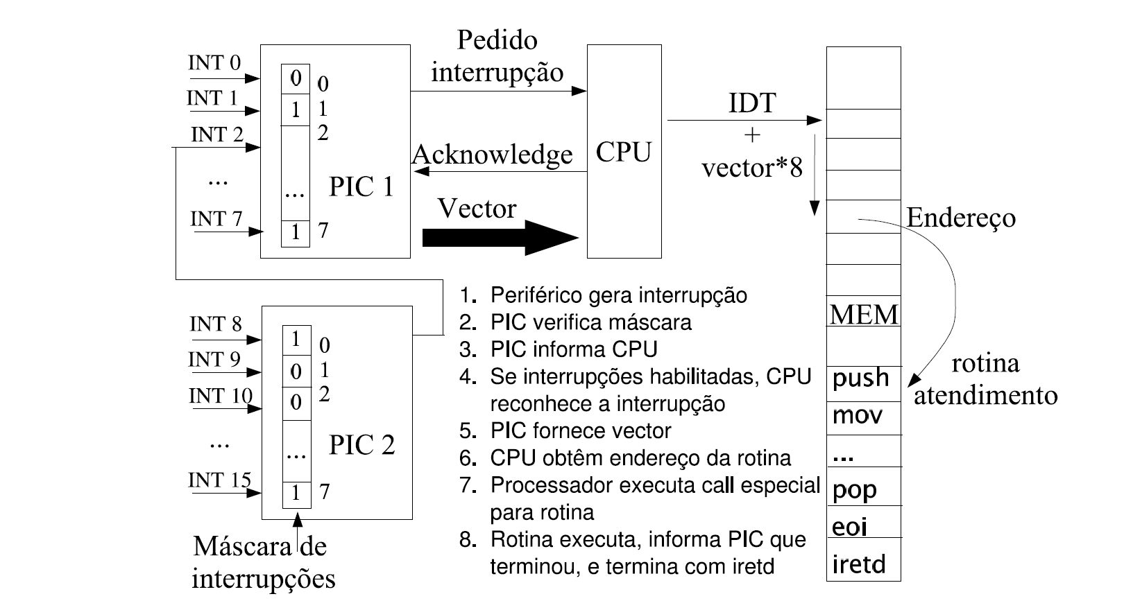
Figure 2 outlines the interrupt mechanism used in the PC. When an I/O device activates its interrupt request line, the PIC will activate the CPU's interrupt line, initiating an interrupt sequence. The CPU will then save the address of the instruction being executed and the flags register on the stack and will disable interrupts, and will respond by activating an interrupt acknowledgment line. When the PIC detects that this line is active, it will put an 8-bit value, which was previously programmed on the PIC, in the data bus. The processor then uses this 8-bit value as an index to a table (the Interrupt Descriptor Table) whose entries contain the addresses of interrupt service routines. The processor will then transfer control to the address of the entry corresponding to the 8-bit value received from the PIC. As a result, the processor will execute the device's interrupt service routine, or interrupt handler, which is responsible for informing the PIC that it has "finished" handling the interrupt, and must terminate with instruction IRETD.
The sequence described in the previous paragraph, assumes that:
Because the PIC does not generate another interrupt for the same device or for another with lower priority until it is informed that the current interrupt has already been handled, it is up to the interrupt handler (IH) to do it, by writing the EOI command (0x20) to the control register. If the interrupt originates on the slave PIC, the IH will need to issue the EOI command to both the slave and the master PICs. Table 4 shows the addresses of the PIC registers and Table 5 shows the IRQ lines and the interrupt vectors for common I/O devices of a PC.
| PIC | Controller Register | Interrupt Mask Register |
|---|---|---|
| PIC1 | 0x20 | 0x21 |
| PIC2 | 0xA0 | 0xA1 |
| PIC 1 | PIC 2 | ||||
|---|---|---|---|---|---|
| IRQ | Device | Vector | IRQ | Device | Vector |
| 0 | Timer 0 | 0x08 | 8 | Real Time Clock | 0x70 |
| 1 | Keyboard | 0x09 | 9 | Replace IRQ2 | 0x71 |
| 2 | slave 8259 | 0x0A | 10 | Reserved | 0x72 |
| 3 | Serial device COM2 | 0x0B | 11 | Reserved | 0x73 |
| 4 | Serial device COM1 | 0x0C | 12 | Mouse | 0x74 |
| 5 | Reserved/Sound card | 0x0D | 13 | Math coprocessor | 0x75 |
| 6 | Diskette | 0x0E | 14 | Hard disk | 0x76 |
| 7 | Parallel port | 0x0F | 15 | Reserved | 0x77 |
An interrupt handler cannot take any arguments nor return any values. Furthermore, it must save all the registers that it uses and must terminate with the IRETD instruction, which resets the stack and the processor to its state at the time the interrupt occurred. Because the interrupts are disabled while the interrupt handler executes, the CPU will not be handle further interrupts, therefore an interrupt handler should be as short as possible; if necessary, the interrupt handler may enable interrupts by executing the STI instruction.
In this lab, you'll use only C language. Because the C language does not provide any operators or standard functions that allow access to I/O ports, you'll have to use functions provided by Minix 3 instead.
Direct I/O port access is a very powerful capability that can be easily misused and that can interfere with the proper operation of the operating system and other processes. Thus, in Minix 3, I/O port access is a privileged operation, and is provided via the SYS_DEVIO kernel call, and several libsys.a functions, that hide the details of making a kernel call from the user-level programmer. For this lab, you may find useful the following functions:
#include <minix/syslib.h>

int sys_inb(port_t port, unsigned long *byte);
int sys_outb(port_t port, unsigned long byte);
As usual, this requires adding a permission to execute this kernel call (SYS_DEVIO) to the file lab3 that you'll have to add to the /etc/system.conf.d/ directory. Furthermore, that file should also specify the I/O ports that the process is allowed to access via this call.
Interrupt handling with Minix 3 is somewhat unusual, because device drivers are user level processes. Indeed, to ensure that the interrupt handler of a device driver does not mess with the kernel, interrupt servicing is also done at the user level by the device driver.
To allow this, the Minix 3 (micro) kernel has a generic interrupt handler, which notifies a device driver when an interrupt it may have to service occurs. Although this might appear strange at first, the truth is that an interrupt handler does not take any arguments and does not return any value. Thus, a simple notification is all that is required from the kernel. Handling of the interrupt proper must be done by the device driver.
The major disadvantage of this approach is that the interrupt servicing latency may become too large for devices that are very fast, such as gigabit Ethernet cards.
To support this model, Minix 3 provides also the SYS_IRQCTL kernel call, and several libsys.a functions, that hide the details of making a kernel call from the user-level programmer. For this lab, you may find useful the following functions:
#include <minix/syslib.h>

int sys_irqsetpolicy(int irq_line, int policy, int *hook_id);
int sys_irqrmpolicy(int *hook_id);
int sys_irqenable(int *hook_id);
int sys_irqdisable(int *hook_id);
All these calls return OK on success and 3 other values on failure.
sys_irqsetpolicy(int irq_line, int policy, int *hook_id)int sys_irqrmpolicy(int *hook_id);int sys_irqenable(int *hook_id)int sys_irqdisable(int *hook_id)Again, subscribing and unsubscribing interrupt notifications, and enabling and disabling interrupts are privileged operations. Therefore, the execution of these operations, and the IRQ lines on which they are allowed to operate must be specified in a file /etc/system.conf.d/ for your process.
The Minix 3 generic interrupt handler uses the Minix 3 interprocess communication (IPC) mechanism to notify a subscriber of the occurrence of an interrupt. This IPC mechanism is essentially a mechanism for sending and receiving messages between processes. Interrupt notifications are a special kind of message supported by Minix 3 IPC.
As a consequence, in Minix 3 a device driver is an event driven service that receives and processes messages, either interrupt notifications from the kernel, or service requests (usually I/O operations) from other processes.
The program that you will have to develop in this lab, is not a standard device driver, in that it does not receive service requests from other processes, but only interrupt notifications from the kernel. Thus, your program should include loop in which interrupt notifications are received and handled. In a standard Minix 3 device driver, this loop is endless. In this lab, you may want to terminate the loop after a few iterations, or on some event. The following code segment illustrates the general structure of the main loop and the Minix 3 functions that should be used.
 1: #include <minix/drivers.h>
 2: #include <minix/com.h>
 3:
 4: int ipc_status;
 5: message msg;
 6:
 7: while( 1 ) { /* You may want to use a different condition */
 8:    /* Get a request message. */
 9:    if ( driver_receive(ANY, &msg, &ipc_status) != 0 ) {
10:        printf("driver_receive failed with: %d", r);
11:        continue;
12:    }
13:    if (is_ipc_notify(ipc_status)) { /* received notification */
14:        switch (_ENDPOINT_P(msg.m_source)) {
15:            case HARDWARE: /* hardware interrupt notification */
16:                if (msg.NOTIFY_ARG & irq_set) { /* subscribed interrupt */
17:                    ...   /* process it */
18:                }
19:                break;
20:            default:
21:                break; /* no other notifications expected: do nothing */
22:        }
23:    } else { /* received a standard message, not a notification */
24:        /* no standard messages expected: do nothing */
25:    }
26: }
Function driver_receive() in line 9, is a function provided by the libdrivers.a library. It should be used by device drivers to receive messages, including notifications, from the kernel or from other processes. The first argument specifies the sender of the messages we want to receive. The value ANY means that the driver accepts messages from any process. The second and third arguments are the addresses of variables of type message and int, which will be initialized, by the driver_receive() code, with the message received and IPC related status, respectively.
The macro is_ipc_notify() in line 13, returns true if the message received is a notification or false otherwise, i.e. if it is a standard message.
The member m_source of type message, used in line 14, contains the endpoint of the sender of the message. The endpoint is an address used by Minix 3 IPC to specify the communication endpoints, i.e. the source and destination of a communication instance. The macro _ENDPOINT_P allows to extract the process identifier from a process's endpoint. The value HARDWARE, used in line 15, is a special process identifier value to indicate a HW interrupt notification. The reason for the use of a process identifier different from the endpoint is that the endpoint of a process may change in time, just like an address, but most of the time we are not interested in the address, but rather on the entity behind that address. Now, you may ask: if so, why use endpoints? Good question, but this is "out of scope" of this course.
Finally, the NOTIFY_ARG macro in line 16 is a reader friendly name for the member of a message type that contains the "argument" of an interrupt notification. This is a 32-bit bitmask with the bits of the active interrupts subscribed set to 1. The bit of an interrupt notification is the one passed in the hook_id argument of the sys_irqsetpolicy() call. For example, if the value used for one interrupt was 2, then when that interrupt occurs, the generic interrupt handler will send a notification to the device driver with bit 2 of the NOTIFY_ARG member of a message set to 1. This scheme allows the kernel to use a single notification message to notify a process of the occurrence of several interrupts on different IRQ lines.
In this lab, as in all other labs, you need only to handle one interrupt. This is because usually a device only uses one interrupt line. Thus, the code in line 17, will just handle the interrupt, or better call the interrupt handler.
However, in your project, the program you'll develop will use more than one device and therefore will have to handle more than one interrupt. Thus, variable irq_set should be a bitmask with the bits corresponding to the hook_id values used in the sys_irqsetpolicy() set to 1. The code in line 17, should then identify which of these bits are set and call the corresponding handler.
As stated above, one of the goals of this lab is to develop a generic module that will be used to create a library, which you will be able to use in the course's project. We could certainly specify the API, as we have done for the previous labs. (Actually, we will also do it for this lab.) But we want you to play a more active role. Rather than being just an implementer of an API, we want you to design an API.
We'll use this lab to show you by example how you can develop a fairly general API, which can be used to operate on the timer/counter, and that you can use to implement the testing functions that we will use to test your code. In the next labs, we'll just specify the testing functions, as we have done above, and it will be up to you to design the API for operating on the I/O devices.
timer_test_config()The purpose of this function is to test your code that displays the status/configuration of a timer. This test function is a simple wrapper that calls directly the function that displays in a human friendly way the status/configuration of a timer. Although such a function is fairly simple, we will implement it in two steps, and therefore, in addition to the function that shows the configuration of a timer, we specify a function that reads the configuration of a timer:
Both functions should be implemented also in timer.c. (You may wish to use the file timer.c, which includes stubs for these functions.) The following paragraphs describe these functions. You can also read their doxygen documentation.
The timer_get_conf() function should read the configuration of a timer as described in Subsection 3.3. It needs not parse the value read from the status register. This function could be designed as a C API to the Read-Back command, allowing to read the configuration of not only a timer but also of several timers and also the counting values of those timers. However, we have decided not to do it because that functionality is seldom needed.
The timer_display_conf() function should parse the value passed in its argument, which is assumed to be the configuration of a timer as returned by the read-back command, an display it in a human friendly way.
timer_test_square()The purpose of this function is to test your code to configure a timer to generate a square wave with a given frequency.
As mentioned above, Minix 3 uses Timer 0 as a time reference to maintain the time of the day and for implementing SW timers (for measuring the duration of time intervals). Thus, when it starts up, it configures Timer 0 to generate interrupts at a fixed rate, by default 60 Hz. Minix 3 then uses a counter that it increments on every Timer 0 interrupt, and uses its value to measure the time -- it expects that counter to be incremented by 60 every second.
timer_test_square() should configure Timer 0 to generate a square wave with a frequency equal to its argument. Thus, if, for example, it is invoked with an argument of 30 (meaning 30 Hz), Timer 0 counter will be incremented by 30 every second rather than by 60. As a result Minix's time of day will rapidly become late, as you'll be able to check by giving the command date
$ date
in Minix and by comparing its output with that generated by running the same command in Linux.
You could easily implement this function by loading the appropriate value into Timer 0 counter. However, this would hardly be reusable (except by cut and pasting). It would not allow us to control, for example, other timers. What we want is that you implement a slightly more general function that is able to configure a timer to generate a square wave with a given frequency:
int timer_set_square(unsigned char timer, unsigned long freq)
This function could then be reused for example to configure the frequency of the tone to be generated by the speaker. Function timer_test_square() would need only to call timer_set_square() with the appropriate arguments. Function timer_set_square() should also be implemented in timer.c. (You may wish to use the file timer.c, which includes stubs for this function.) For more information about it please read its doxygen documentation.
IMP: Make sure that you do not change the 4 least significant bits (i.e. the counting mode and BCD vs. binary couting) of the control world, which are programmed by Minix at boot time. (This requires you to read the Timer 0 configuration before you change it.)
timer_test_int()The purpose of this function is to test your code that handles interrupts generated by Timer 0. With that in mind, it should print a message on every second, using the function printf(), for a time interval whose duration is specified in its argument. These messages will appear on the console and will be appended to the file /usr/log/messages. Thus, if you are on a terminal different from the console, you can still see these messages by giving the command:
$ tail -f /usr/log/messages
Again, you could implement the entire functionality required-- subscribing an interrupt, handling the interrupts and unsubscribing an interrupt -- inside timer_test_int(), by invoking the right Minix 3 kernel calls. Again, that would not be reusable. More interesting is to design functions that you can use later in the project:
void timer_int_handler()
int timer_subscribe_int()
int timer_unsubscribe_int()
which should be implemented in a file named timer.c. (You may wish to use the file timer.c, which includes stubs for these functions.) The following paragraphs describe these functions. You can also read their doxygen documentation.
As stated above the main use for the periodic interrupt generated by Timer 0 is as a time reference that can be used to measure time. This requires incrementing a counter on every interrupt. Thus all timer_int_handler() needs to do is to increment a global counter variable.
The implementation of timer_subscribe_int() is straightforward. You must call the sys_irqsetpolicy() and the sys_irqenable() calls, described in the paragraph on interrupt subscription in Subsection 5.2 . The policy you should specify in sys_irqsetpolicy() is IRQ_REENABLE, so that the generic interrupt handler will acknowledge the interrupt, i.e. ouput the EOI command to the PIC, thus enabling further interrupts on the corresponding IRQ line. The implementation of timer_unsusbscribe_int() is even simpler.
Although these functions can be reused to (un)subscribe Timer 0 interrupts, they cannot be used to (un)subscribe interrupts for other I/O devices. Although, we would like to be able to do that, it is a bit too early to devise a general API. It requires more experience with the use of interrupts on Minix 3, as well as the use of some C features that you do not know yet.
This is even "more true", for the "interrupt loop", i.e. the loop for receiving an interrupt notification. Thus, for the time being, I suggest that the interrupt loop be included in timer_test_int().
Compilation of your program should be done with the help of make and a makefile, as you've done in Lab 1. Thus you should create your own makefile for this lab, by modifying the makefile that we have provided for Lab 1. Note that in this lab you do not use libvt.a, so you should remove it, otherwise you will have to copy it into Lab 2's build directory.
Once you have modified the makefile, you can compile your code by giving the following command as user lcom:
$make
Your program invokes functions that are privileged. Thus, before you can run it, you need to add a file named lab2 to the /etc/system.conf.d/ directory to grant your program the necessary permissions.
Unless you use privileged functions that are not really necessary, the following entry is enough:
service lab2
{
        system
                DEVIO
                IRQCTL
                ;
        ipc
                SYSTEM
                rs
                vm
                pm
                vfs
                ;
        io
                40:4      # i8254 ports
                61        # port for speaker control
                ;
        irq
                0         # TIMER 0 IRQ
                ;
        uid     0
                ;
};
Once you have created the file with the permissions, you can execute your program using the service command. Given that your program should be privileged, you must run your it as user root. Thus, assuming that you are in the directory /home/lcom/lab2, you can issue the following command as root:
# service run `pwd`/lab2
The `pwd` expression evaluates to the output of the command pwd, which returns the present working directory (/home/lcom/lab2, according to our assumptions). This is simpler than having to type the full path:
# service run /home/lcom/lab2/lab2
You should submit your code to the SVN repository as you develop and test it. This code should be under directory lab2, which should be at the top level of the SVN repository of your Redmine project.
The deadline for the submission is at the end of your second class of this lab. Because, some sections cannot stay in the lab after the end of their classes, you have only a 10 minutes tolerance. That is we will grade the latest submission 10 minutes after the end of your 2nd class. Please make sure that you are sufficiently familiar with SVN to avoid last minute problems.
If, in spite of all the advices and warnings, you have problems submitting your code via SVN, in this lab you'll be allowed to make your submission by email. For that, by the lab deadline (including tolerance), you should send me an email with a zip archive with your source code (archives including object files or executables will be penalized according to the size of the archive). The subject of this email must be LCOM: Lab2 by <group-name>, where <group-name> is the name of the group whose code is being submitted, e.g. T2G01. Late emails will just be discarded, other email submissions incur a minimum penalty of 20%.
This lab is based on a lab by João Cardoso and Miguel P. Monteiro for DJGPP running on Windows98.